Copyright © 2020 M.Kenny, A.McGuire and E.Jones. All Rights Reserved
No parts of this website maybe copied or reproduced without permission
E-Portfolio: Working Drawing
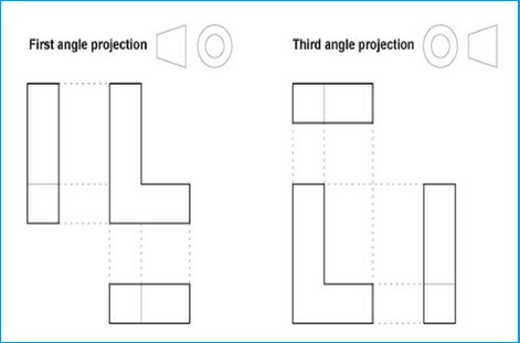
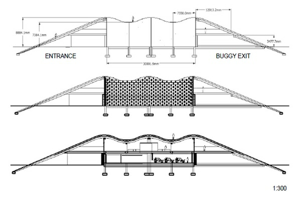
A working drawing also known as an orthographic
projection is a method that allows someone to represent
a three-dimensional object on a two-dimensional piece of
paper. By drawing the object for a various angles, the
artist is able to show how the object looks in the real
world. The process is called orthographic projection. A
working drawing should be set out in a certain way
(standardised) that all manufacturers across the UK can
use to make the product in real life from your drawings.
In your design portfolio, you should show that you have:
●
|
used an appropriate template
|
●
|
used a basic range of CAD drawing and editing commands
|
●
|
used the correct tools to produce the correct geometry
|
●
|
used the correct tools to manipulate views on screen
|
●
|
used a range of further CAD commands including coordinates, features and modification techniques
|
●
|
used dimensioning and hatching techniques
|
●
|
produced a drawing that meets the expected standard (BS8888) saved the drawing in the correct format.
|
Orthographic drawings usually consist of a front view,
a side view and a plan view, but more views may be
shown for complex objects with lots of detail.
A drawing board and parallel motion or T-square is used
to project one view from another. Orthographic drawing
may be done using first angle projection or third angle
Projection. An orthographic projection of the shape on
the right is shown below.
HOW TO LAYOUT YOUR A WORKING DRAWING
Using CAD in your design portfolio and developing your in CAD allows you to produce
orthographic drawings very quickly. This allows third parties to manufacture them
provided you lay them out using the standardised method. Information found on a working
drawing / orthographic drawing:
- All views required for manufacturing.
- All required measurements (called dimensions).
- A standardised format for working drawings.
- A parts or cutting list which includes all the information needed to make each part
of the product.
Below are two step by step guides to produce an orthographic drawing for a product.
Adapt them to to suit your own designs. Click on the owl button to bring up the tutorials
and follow step by step.
This page is entirely up to you how you how you present it and can be a mixture of
some of the details below that you are going to explore and your own ideas. You need
to present the following:
- Front views
- Side Views
- Top Views
- Dimensions
- Correct title block and border
You can also present the following:
- details of components
- materials
- assembly instructions
- sectional drawings
Sectional and assembly drawings
Some products may need a section drawing to give extra structural information, or
an assembly drawing to show how parts fit together.
As already explained orthographic drawings usually consist of a front view, a side
view and a plan view. This allows third parties to manufacture them, as shown in
the two videos below.
STEP BY STEP GUIDE TO A WORKING DRAWING
HOW TO LAYOUT A WORKING DRAWING